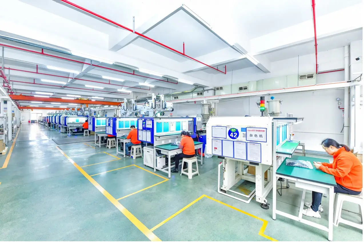
An injection-molded part can leave the press looking acceptable and still develop visible marks later. A pale area may appear after assembly, a crack may form around a boss, or a component may gradually warp after it has cooled completely. These are not necessarily new defects created after production. They can be visible evidence of stress that was already locked into the polymer during molding.
Understanding injection molding stress marks therefore requires more than examining the final surface. HordRT explains that residual stress can originate from both flow-induced effects during filling and packing and thermal effects during cooling. The resulting stress may later manifest as whitening, cracking, warping, dimensional variation, or reduced part durability.
Why Stress Marks May Appear After the Part Looks Finished
The moment of ejection is not necessarily the end of the material’s response to molding. During filling, polymer chains become oriented by the direction and speed of melt flow. Cooling then causes the material to contract, but different regions may cool and shrink at different rates. Some of that deformation is constrained by the surrounding material, leaving residual stress inside the finished component.
HordRT identifies high shear during injection as one source of flow-induced stress and uneven cooling as a source of thermal stress. Both can remain in the part after ejection rather than becoming immediately visible.
A later event can expose the problem. Assembly force, flexing, chemical exposure, or ordinary service loading may allow the stressed polymer to relax or crack. A part that appeared visually acceptable at inspection can therefore reveal a weakness only after it has entered the next stage of the product.
That delayed behavior is why visual inspection immediately after molding does not always provide the complete picture.
The Location of the Mark Can Reveal Its Origin
Where a mark appears often provides more useful information than how dramatic it looks. Stress concentrated around a gate can suggest that the polymer experienced excessive shear or restricted flow while entering the cavity. A defect near a thin section may indicate difficult filling or hesitation. Marks around ribs and bosses can point toward geometry-related stress or uneven cooling.
HordRT’s guidance recommends controlling gate placement, runner balance, and venting as part of stress reduction. Its approach positions gates to support appropriate filling and packing while using balanced runners to reduce differences between cavities.
The same principle applies to cooling-related defects. A thick section surrounded by thinner walls does not solidify in the same way as a uniform section. Different shrinkage rates can leave internal tension that eventually becomes visible as deformation or cracking.
Ejector locations create another diagnostic clue. If whitening or distortion consistently occurs around ejector pins, the molding process may be producing a part that is difficult to release rather than one that is inherently defective in its material. Consequently, mapping the defect location onto the mold layout can narrow the investigation considerably.
Whitening, Cracking, and Warping Tell Different Stories
Not every stress-related defect has the same physical expression. Stress whitening appears as a pale or cloudy area in the plastic. HordRT identifies whitening as an indication that high stress can cause polymer chains to separate or deform locally. Cracking represents a more severe condition in which internal tension exceeds the material’s ability to withstand it.
Warping behaves differently. Instead of producing a localized surface mark, accumulated stress can cause the entire component to twist, bow, or deviate from its intended geometry. HordRT links this behavior to anisotropic shrinkage, where the material contracts differently along and across the flow direction.
Dimensional instability can be another manifestation. A part may technically remain intact while critical dimensions drift because different regions of the component relax at different rates.
These distinctions matter during troubleshooting. Whitening around a gate should not automatically trigger the same corrective action as warping across an entire panel. The visible symptom provides a starting point, but the physical mechanism determines what should be changed.
Assembly Can Expose Stress That Molding Left Behind
Some of the most confusing cases occur when parts pass molding inspection but fail during assembly. A molded housing may require a screw to be driven into a boss, a snap-fit may need to deflect, or two mating components may need to be pressed together. Those operations introduce additional mechanical loads.
If the molded part already contains residual stress, assembly can push a vulnerable region beyond its remaining strength. A small whitening mark may become a crack, while a distorted interface may prevent components from fitting correctly.
HordRT notes that significant internal tension can act as a preload, reducing the part’s ability to tolerate external forces or chemical exposure and potentially shortening service life. That means stress analysis should not stop at the molding machine. The complete product sequence matters.
Engineers should examine whether the defect appears before assembly, immediately afterward, or only after functional testing. Comparing those stages can help distinguish a molding-originated problem from damage introduced by downstream operations.
Material and Geometry Determine How Visible the Damage Becomes
The same molding conditions do not produce identical stress behavior across every resin. HordRT notes that high-flow materials can require less injection pressure, potentially reducing flow-induced stress. It also distinguishes between amorphous materials such as ABS and PC and semi-crystalline materials such as nylon and PP, which can exhibit different shrinkage and anisotropic behavior. Fiber reinforcement can further increase directional shrinkage depending on fiber orientation.
Geometry adds another layer.
Abrupt wall-thickness changes can create uneven filling and cooling. Sharp corners can concentrate stress. Heavy ribs and bosses can create localized differences in material volume and cooling behavior.
HordRT’s design guidance recommends maintaining relatively uniform wall thickness, using appropriate radii, and controlling rib and boss proportions to reduce stress-related problems.
Material and geometry should therefore be evaluated together. Switching resin without correcting an inherently stressful geometry may only move the problem. Likewise, redesigning the part without considering the selected material’s shrinkage behavior may leave another source of instability unresolved.
Turn Stress Marks Into a Process Diagnosis
The most useful response to injection molding stress marks is not to adjust every molding parameter simultaneously. A better investigation begins by documenting the defect.
Record where the mark occurs, when it becomes visible, whether it is associated with a gate, rib, boss, ejector, or sharp corner, and whether it changes after assembly or environmental exposure.
The next step is to compare those observations with the molding process. HordRT recommends addressing stress through a combination of part design, mold engineering, processing conditions, and material selection rather than relying on inspection alone. Its engineering support includes DFM review and CAE/Moldflow analysis for evaluating gate locations, weld lines, and shrinkage patterns before tooling is finalized.
Process changes can then be targeted. Injection speed and melt temperature influence flow stress; holding pressure affects packing; cooling time influences dimensional stability after ejection. HordRT specifically notes that excessive holding pressure can pack stress into the component, while insufficient cooling can allow a part to warp after leaving the mold.
Injection molding stress marks are most useful when treated as evidence rather than merely as cosmetic defects. Their timing, location, and appearance can reveal what happened inside the cavity before anyone could see the problem.
A reliable solution comes from connecting that evidence back to the complete molding system: part geometry, resin behavior, gate and runner design, thermal balance, packing, and ejection. Once the origin is understood, corrective action becomes much more precise—and the same failure mechanism can be prevented rather than repeatedly repaired on finished parts.

