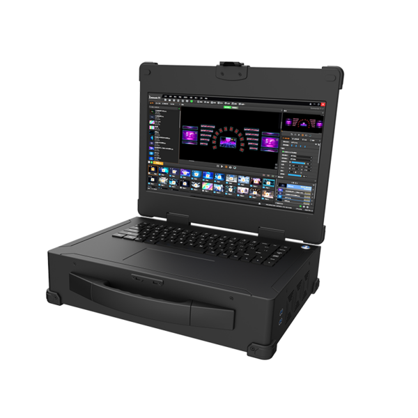
The clearest distinction begins with a simple question: which device creates the pixels that the audience sees? If stored media, live layers, web sources, and timed cues must be rendered into a program canvas, a multimedia server performs the content-generation role.
If complete external signals already exist and need to be acquired, scaled, routed, windowed, or spliced, a video processor performs the signal-manipulation role. Large LED systems may use both, but assigning the same responsibility to two devices adds complexity without improving the result.
Locate the Origin of the Program Canvas
A multimedia server starts with assets and instructions rather than only finished video inputs. It decodes media, composes layers, follows a timeline, and maps the resulting canvas to one or more outputs. The operator can change clip order, transparency, scene transitions, or Picture-in-Picture placement before the final frames leave the machine.
Custom-canvas and pixel-to-pixel workflows are important when the LED wall does not follow a standard television raster. Placing scaling in both devices can soften fine detail and complicate troubleshooting. Once the canvas owner is assigned, the other stage should normally preserve that geometry unless a documented conversion is required at the display boundary.
One recorded scaling stage keeps that responsibility unambiguous. A processor normally receives a signal whose frames have already been created. It can scale that signal, crop or duplicate it, place it in windows, and distribute it across outputs.
Some processors add overlays or background layers, but their central job remains real-time treatment and routing of external sources. The project diagram should show where content becomes a finished frame, because that boundary determines which device owns creative composition.
Compare Media Layers with External Source Windows
Layer count can sound similar on both product types while referring to different resources. A multimedia server layer may be a decoded file, web page, network feed, subtitle, image, or effect inside a rendered scene. Processor windows are usually live input regions taken from HDMI, DisplayPort, SDI, DVI, IP, or other source cards.
The first consumes decoding and rendering capacity; the second consumes input, scaling, window, and routing capacity. These workloads also fail differently. A server can miss a frame deadline because a codec, effect, or layer stack is too demanding.
A processor can reach a limit on active inputs, windows, output routes, or interface bandwidth. Procurement records should therefore keep server media tests separate from processor routing tests even when both products advertise 4K, 8K, layers, or splicing.
Map Outputs to the Required Display Architecture
Output design may determine whether a multimedia server can feed the display directly or should pass through additional processing. A server can render an ultra-wide canvas across several synchronized video outputs.
A processor can then receive those feeds, combine them with cameras or presentation sources, and route the result to conventional video outputs or, in an integrated LED platform, to Ethernet ports serving the LED transmission chain.
For server-led canvas generation, Kystar’s FP8/FP12/FP16 servers provide 8K hardware decoding and support up to sixteen synchronized 4K@60Hz output channels for large-scale canvases. Its workflow also covers arbitrary output splitting and recombination, preset scenes, common media playback, web windows, NDI capture, cascading, and KFS frame synchronization. Those functions create and coordinate the program canvas; they are not simply a larger input switcher.
Use Processor Capacity for Real-Time Acquisition and Routing
A video processor is appropriate when the project begins with external sources that must remain live. Kystar SEn and SHn families focus on acquisition, scaling, windowing, routing, and splicing across large numbers of outputs or LED network ports. Card configuration determines which interfaces, routes, and capacities are available.
The processor can reorganize complete signals without requiring the show to be authored as media-server scenes. A multimedia server may still feed that processor as one or several of its sources. In such a chain, the server renders the authored program while the processor combines it with cameras, conference systems, or other live feeds.
Clear naming at the interface prevents operators from scaling the same image twice or applying a crop in two locations. It also makes backup planning more precise, because the team can decide whether it must replace the rendered program, the live routing stage, or both.
This role is especially relevant in control rooms, command centers, studios, and venues where operators must place many changing sources on several displays. A processor may also provide a central point for preview, switching, and display composition. It does not automatically replace the timeline, media decoding, custom-canvas rendering, or asset management performed upstream.
Let the Workflow Define the Division of Labor
Hybrid systems become easier to operate when the multimedia server and processor have explicit boundaries. The server can own stored and network media, time-based cues, effects, and pixel-accurate rendered outputs. The processor can own external-source selection, live window layouts, routing, and final distribution.
EDID, raster, refresh rate, color format, synchronization, and backup behavior must be documented at the interface between them. Kystar supplies both product families, so model selection can follow the missing function rather than a broad product label.
A media-led show may need Kommander alone; a live multi-source wall may need SEn or SHn; a complex venue may connect the two. The correct answer is not which category is universally stronger. It is which device should create the pixels, which should manipulate completed signals, and whether the project genuinely requires both stages.

